
Similarly to the structure of the previous couple of 3D lessons, we recapped a key part of one of the old sessions, learned new skills and/or techniques, and then spent the remainder of the time modeling something, most likely using said skills.
Firstly, the recap. We were tasked with making a spiral staircase, to remind ourselves of the duplicate special tool. The staircase part was very easy since I remembered well that tapping ‘D’ allows for quick duplication and I made a spiral within the first few minutes. The tricky part was with the extension after this; trying to add a railway. First, I created a cylinder and stretched that upwards through the centre of the model, to make a base for the stairway.

I tried to use duplicate special to create the rails, by making one, adding a duplicate, rotating it/moving it slightly, and then tapping ‘D’. No matter what I did, this didn’t work because the dupes didn’t follow the stairs exactly. They may have curved slightly in the beginning, but after a couple of times, they just went straight ahead. Besides, I didn’t know how I would make them go upwards, even if they spiralled correctly.

The obvious, quick and simple solution here, that I missed, was to create the first step with a railing already added on and combine the two shapes so that they are one mesh. Doing so would not only allow the duplicate special tool to properly work but also speeds up the whole process.


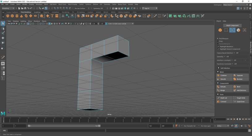
After the recap, we were introduced to the fill option and bridge function and reminded of the correct way to import and export. Firstly, we extruded upwards from the top face of a cube three times, to create a model that looked like a stack of four cubes, but wasn’t. We extruded once again at the top, but from the side, so that we had an upside-down ‘L’.

Next, we selected all of the faces on the underside/inside, and deleted them, creating the all too familiar black hole. In edge mode, we were shown and told to select all of the edges on two sides (right and left), go to ‘edit mesh’ and click ‘bridge’. Of course, we had done this before, so the resulting fixed model was not a surprise, but we hadn’t used the techniques properly with a more complex model. It was beneficial to apply both fixing methods to something like an extruded cube so that the differences between them could be highlighted and understood.


Having said that, we deleted all of the faces again and this time, selected all of the edges, all the way around the hole. We then went to ‘mesh’ and ‘fill hole’, making the space fill up. Like with the single cube we applied this to last time, we saw that the geometry was missing.

To fix this, we had to once again, rely on the multi-cut tool. Using it, we clicked on a vert and then the one opposite it, connecting them both and creating an edge. It wasn’t as simple as repeating this for the next pair, however. We had to quit each time two verts were connected, otherwise the edge like would carry over, criss-cross, and make all sorts of complicated cuts that would mess up the model. So each time I finished with two verts, I clicked ‘Q’ and did the same thing for the next ones. After completing the cutting, I realised that there was something different about the L, which we didn’t see before when using the fill option on a single cube. The area near the top had a strange light-to-dark gradient.
Apparently, this is because the model was trying to figure out what we had done, and was processing the actions in a weird way. And although the gradient was somewhat pretty, it had to be changed back to normal. To do this, we selected the shape entirely, shift + right-clicked to get to the ‘soften/harden edges’ option, where we chose ‘harden edges’. Upon clicking this, the shaded area at the top of the underside reverted back to the normal solid shadow.

The bridge function was certainly faster, but ‘fill hole’ allowed you to change the geometry as desired. Ultimately, it is good that Maya has both options, for artists to work with and choose from depending on their model.
The tutor showed us how some of these techniques could be applied to speed up the modeling workflow. It was a good chance to see how 3D modelers combine and mix different skills to achieve a particular result as fast as possible. First, we were all asked to model the object on the board by ourselves, which looked like this:

Being a simple, two-step extrusion, I got this finished in no time. Next, using the options panel for ‘mirror’, I mirrored the object along the right axis using ‘world’, as instructed. Once we reached this stage, we followed along with the demo. The first step was to separate the objects (mesh) and delete the two front faces of the extruded part of each shape to create holes. We moved one of the objects further up and combined them again, which was interesting since I never thought about how you could alter objects and re-combine, allowing for quick duplication. Next, we joined the objects by selecting all of the edges on both holes and using the bridge function. An extended cube appeared, stretched between the first hole to the second.
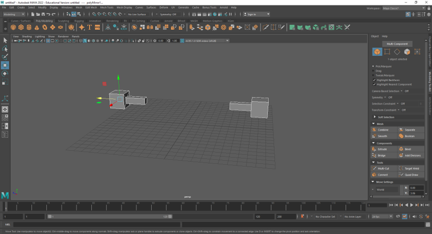

I hadn’t expected this and was surprised to see that ‘bridge’ could be used for something like this. After connecting them, we could extrude out of both cubes at the same time, repeat the bridge steps and then duplicate. Each time the model grew in size, we could duplicate again, and quickly create a unique structure.


It was explained to us, how something like this was extremely helpful for backgrounds, such as when creating alien cities. At the mention of ‘alien’, I wanted to make my model a bit more interesting, so I added two disks to the side of the structure, to ramp up the sci-fi vibe. It looks like some sort of ship, but I would have to continue modeling it to add more conventional features. For now, I was just playing around, and am content with leaving it looking like some interesting, albeit bizarre alien object.

– Main Task –
After going through all of these new/revised techniques, we advanced to the main task. We would be modeling a chair and table, to create a scene and a nice final render. I created a new scene in Maya and imported the images of the chair from the front and side. We were challenged with only using these two views for this modeling task, since, ideally, with something like this, you shouldn’t need to go in perspective mode at all, other than for quick checks. We were also shown how to change the view-port in two-view, by going to panels at the first bar at the top, into ‘orthographic’ and then selecting from whichever option. This was very useful to me since I do like to check how the model is looking from time to time in 3D mode. Of course, in order to not keep flicking back and forth to it every minute or so, we would be using verts to model, and only drag selecting unless a specific corner needs to be moved on its own.

I inserted a cube and positioned it in front view first, to match at least one of the corners of the panel that I would be building. Then, by drag selecting the verts, I moved down each side to make it the correct size and match the orthographic. I did the same in side view afterwards, using the arrows to move it forward or back and perfectly match the beams. As always, having ‘x-ray’ and ‘wireframe on shaded’ helped me see both the template and the primitives. After creating both of the legs, I would usually duplicate them both, and move them across. However, I decided that it would be easier to just mirror the entire model at the end, so I would only be modeling half of the chair, therefore only needed to build one set of legs.
My first obstacle was the curved beam underneath the armrest. I created the cube, scaled it and moved it into position, and tried to use bevel to simulate the curve at the bottom. This didn’t do anything, so I tried to use SMP instead (smooth mesh preview), but even with added edge loops, it was far too round.

After requesting some guidance, I was given the quick tip: “use the verts”. It was truly all I needed. I remembered the way that we build the spout of the Utah Teapot and used the multi-cut tool to add edge loops to the panel, thereby creating more verts and enabling me to scale them and create the rounded edge.

One of the most interesting and challenging parts of creating the chair was having to decipher the 2D images and translate them into 3D models in my head. For example, I couldn’t exactly make sense of the lines under the seat, and how they worked in both images; in the front one, there are 2, but in the side one, there is only 1, which made it a little confusing. A friend, the tutor and I discussed it together and figured out what had to be done. Underneath the seat was a beam for the front, and two at the sides for the legs, not an actual solid wooden block like I initially thought. This meant that when creating the beams, it was necessary to only stretch them out for half of the distance of the first leg so that there would be enough space for the front panel as well. Of course, when I built the beam joining the two legs, I also inserted two edge loops in order to curve the top to match the seat.

After finishing the side and front beam, I set to work on the actual seat, which seemed to be multiple panels joined together in a comfortable slope downwards. I created a cube for the first, stretched it out to the centre line of the chair using the front view and also moved the verts to make it fit better with the template. I then duplicated it, moved it to the side, rotated it slightly, and adjusted the verts when necessary. I repeated this process for each one, and soon enough the seat was complete.

Next, I moved on to the back of the chair. Since I was only modeling half, I would only be creating the first three panels. They were quite simple to create, but since they were of different sizes, I had to duplicate them each time, move them into position, and use the arrows keys to move the tops up or down. They also weren’t perfectly symmetrical, meaning at some point, I moved the verts on one side at the top a little further down than the other side. When I was working in side view, this confused me for a solid three minutes; I thought that I had an extra edge loop, and I could not figure out where it came from. I eventually realised that it was just the edge that was lower than than the other side being shown through a line a little lower than the top of the panel. Another challenge that I faced with these panels was that if I was to move them in position in side view, they would disappear from the front view since they were behind the template. So, I had to create one, duplicate it, move it back, and then work on the dupe in the front view, before doing the same thing and moving it into place in side view.

Lastly, I created the support beam behind the panels of the back, and it was time for the final step – mirroring! I pulled up the window for ‘mirror’ and selected the right axis and option. ‘Object’ is the one I chose at first since I didn’t want the space to be duplicated, just the model. However, after trying every axis and both ‘+’ and ‘-‘ for the axis direction and seeing that nothing was working, I had no choice but to try out ‘world’. It worked first try! My chair was perfectly mirrored and complete. Once I thought about it logically, I figured out the reason for this. ‘World’ mirrors the space, yes, but the space from where? It mirrored everything from the centre lines of the grid, and since I had modelled the chair half exactly along the gridline then World would only mirror the chair because there is no gap or space to mirror otherwise. Still, I wasn’t sure why Object didn’t work.

After seeing my chair in perspective mode without the templates, I was really happy and proud. The time I spent creating it was worth it, and it looked awesome completed. Once again, time ran out (this seems to be a recurring problem with me) and I didn’t manage to get onto the table. However, I was determined to get a somewhat decent scene, so I duplicated the chair, positioned them both in a more realistic position (less rigid) by rotating them and spacing them comfortably apart, and got to work on a simple coffee table. I used a cylinder, flattened it and scaled all of the top vertices outwards. Then, using extrusion at the bottom, I made a stand, and voila, a quick and easy table. If I had more time, I would have also created a vase or bowl for the top, but I wanted to move on to rendering.
The finishing touches included creating a poly plane, assigning a material to each object in the scene, adding a skydome and playing around with the colours and lighting.


Final Render

This was a great modeling lesson. Every time that we get to model something new from a template, I get quite excited, since it is a chance to gain more experience and apply skills and techniques from the very first day of opening Maya to now. With each completed model, I become more confident in my capabilities and satisfied looking back at every render. The chair, in particular, made use of my mirroring and problem-solving skills and modeling with verts. I still don’t like extruding with verts, but they are very useful with hard surface modeling and with shaping the primitives into more specific moulds. If I had more time, I would improve the scene by creating the intended table, some objects to go on top and add more life, and perhaps even some texture, such as wood for the chair and glass for the tabletop.
Pre-Vis
For the remainder of the lesson, we looked into some key modeling know-hows as well as pre-vis in 3D.
What is Duplicate Special?
This tool enables users to speed up workflows and ensure that there is a mathematically accurate and equal distance between duplicated 3D objects within Maya.
What are some examples of 3D models that would benefit from the use of duplicate special?
Railings
A fan
A watch
A spiral staircase
An environment e.g. office workstation, roof tiles etc.
A bike e.g. the wheels or spokes
These are good examples because they have lots of small repeating details/parts that duplicate special could make much faster to create. Modeling things such as the cogs in a watch or the tiles of a roof individually would take far too long and would hinder the artist, so duplicate special comes in to allow for faster modeling. It also ensures that each object or group of objects is the same, in terms of accurate appearance and distance.
What is Pre-Vis?
The process of making stripped-down versions of film scenes before making them. This is usually made within a 3D program, where creating rough versions of more complex shots in a movie sequence can be done proficiently.
